


A Low-Cost Water Sensor Circuit
This article describes a very useful but simple water sensor circuit. This water sensor turns on (or off) an LED or other attached load when a probe touches water.
Overview and Application
Suppose you have a project in mind where you need to determine if the water in a container (rain barrel, fish pond, etc.) is above or below certain level. Figure 1 shows an application of a water sensor circuit that just might match your needs. The water sensor circuit will detect whether the water is touching the sense probe, and it will activate an LED or other attached device. The ground probe shown in the figure remains in the water, but it can also be mounted at the same level as the sense probe (the function of the water sensor circuit is to determine if both probes are in the water). The 5 V power supply can be a lab power supply, a "wall wart," or three 1.5 V batteries in series (the circuit will work fine using 4.5 V instead of 5 V).

Figure 1. For this application, the water sensor circuit will detect if the water is above or below the level of the sense probe.
Note: This water sensor is indented for experimental use only and is not intended for critical applications such as controlling basement sump pumps or water alarms in situations where damage can be caused. This sensor is intended for water and should never be used for any other fluid.
Circuit Schematic
The schematic for the sensor is shown in Figure 2. The circuit uses an LM339 comparator to compare the voltage at a sense probe to a reference voltage VREF. For demonstration here, the sense probe and ground probe are simply breadboard jumper wires with stripped ends.

Figure 2. The schematic of the water sensor circuit that turns on a load when the water rises above a certain level, causing the sense probe to touch the water.
How the Circuit Works
The voltage VPROBE at the comparator's inverting input (-) depends on whether the sense probe is touching the water. When the sense probe is out of the water (an open circuit), the voltage VPROBE is 5 V. Since the input impedance of the comparator is very high, very little current flows through the 1 MΩ resistor (R3), and therefore, there is almost zero voltage across the 1MΩ resistor. Consequently, the voltage at the sense probe and the comparator's inverting input is equal to VS (5 V) when the probe is out of the water.
When the sense probe is in water, the water acts as a resistance between the sense probe and the ground probe. This resistance sets up a voltage divider between VS (5 V) and ground as shown in Figure 3.
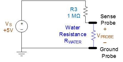
Figure 3. When the sense probe touches water, a voltage divider between VS and ground is set up by R3 and RWATER (the water resistance between the probes).
The voltage VPROBE is calculated by voltage division using
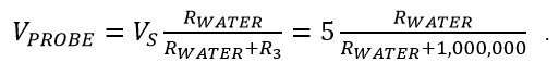
Using this equation, if RWATER is less than 1 MΩ, then the VPROBE will be less than 2.5 V. We will assume that the water resistance is less than 1 MΩ (and we are not trying to detect the level of purified water, which actually has rather high resistivity).
This means that we can determine if the sense probe is touching the water by determining if the sense probe voltage VPROBE is below 2.5 V. If VPROBE is above 2.5 V, the sense probe is not touching water. If VPROBE is below 2.5 V, the sense probe is touching water. This voltage comparison is done using the comparator.
The reference voltage VREF used for the comparison is created by two 100 KΩ resistors (R1 and R2). Since very little current flows into the high-impedance non-inverting input of the comparator, the resistors R1 and R2 form a voltage divider to create a reference voltage of 2.5 V at the non-inverting input of the comparator.
The LM339 contains four comparators. This circuit uses one of those comparators. The LM339 comparators have open-collector outputs. This means that when VPROBE is less than VREF, the comparator leaves its output floating (not connected to anything internally). When VPROBE is greater than VREF, the comparator essentially connects its output to ground internally.
Transistor Q1 controls the current through the LED D1 (or other load such as a small relay if connected in place of D1). When VPROBE > VREF, the comparator connects its output to ground, and no base current flows through Q1. This means that the transistor is in cutoff and no current flows through the LED (or other load) when water is not touching the sense probe. When VPROBE < VREF, the comparator leaves its output floating, and base current flows through Q1. The base current saturates the transistor and turns on the LED. Resistor R4 has a value that saturates the transistor to allow about 20 mA to flow through the LED when water touches the sense probe.
The following table summarizes how the circuit in Figure 2 operates.
| Probe State | Probe Voltage | LED State |
|---|---|---|
| Out of Water | VPROBE > VREF | OFF |
| In Water | VPROBE < VREF | ON |
Testing the Circuit
The circuit was constructed on a breadboard for testing and for a short-term application. These are the components used:
| Reference Designator |
Description | Distributor & Part Number |
|---|---|---|
| U1 | Comparator IC, LM339 | Digi-Key 2N3904FS-ND |
| D1 | Green LED, LTL-4233 | Digi-Key 160-1130-ND |
| Q1 | Transistor, 2N3904 | Digi-Key 2N3904FS-ND |
| C1 | Capacitor, 0.1 uF | Digi-Key BC2665CT-ND |
| R1 through R5 | Any common resistors e.g., Vellemen K/RES-E12 |
Jameco (kit) 2131039 |
Figure 4 shows the circuit on a breadboard. The ground probe is in water, and the sense probe is not touching the water. The green LED is off.
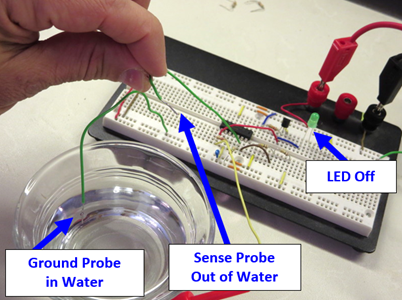
Figure 4. Testing the water sensor circuit (sense probe out of water).
Figure 5 shows the same circuit with the sense probe touching the water. The green LED is on.

Figure 5. Testing the water sensor circuit (sense probe in water).
For this circuit used in a short-term application, two breadboard wires were used as the sense and ground probes. For longer-term applications, probe materials would need to be investigated to determine resistance to corrosion and associated reliability of detection.
An Alternative Circuit
The alternative circuit shown in Figure 6 will activate an LED (or other load) when water falls below a certain level. This circuit operates in the same way as the previously described circuit, except that the inputs to the comparator are swapped. When the sense probe is not touching the water, the voltage at the comparator's non-inverting input is 5 V, which is greater than the reference voltage VREF (2.5 V) at the comparator's inverting input. As a result, comparator's output pin is left open internally, and the current from the 5 V supply through the 22 KΩ resistor saturates the transistor, turning on the LED. Therefore, when the sense probe is in water, the LED is off, and when the sense probe is out of water, the LED is on.

Figure 6. The schematic of an alternative schematic for a water sensor circuit that turns on a load when the water level falls below a certain level and the sense probe no longer touches the water.
Summary
The two water sensor circuits in Figure 2 and Figure 6 are great for electronics projects, providing a way to sense the level or presence of water. The circuits use a minimal number of low-cost, common parts that can be assembled on a breadboard or a custom PCB.
